

>>> Get It! (meshtex_3.0beta.zip) <<<
MeshTex adds operations for patch mesh texturing to the GtkRadiant level editor. These operations generally are concerned with having precise control over where texture coordinates end up on the mesh surface — especially along the edges — or precisely specifying the scale and/or tiling amount of the texture. You can download a beta version below, with some caveats: the documentation could be a lot better, and some texture placements that you attempt to do with these operations may be defeated by the way that Quake 3 actually renders the patch mesh in-game (more about that below).
Also of course it only works with GtkRadiant 1.5, not with the completely revised 1.6 series. It will probably also work with at least some of the many forked variants of 1.5 out there, and it is included by default in the netradiant-custom distribution.
Back in 2001 I had noticed some problems with the way I textured patch meshes in jlctf1, and I wanted to be able to handle those operations better in future maps. So I wrote a quick and dirty plugin called PatchAlign for GtkRadiant 1.1-TA. My main concerns were to have better control over what parts of the texture ended up on the mesh edges and to scale the texture in ways that looked the same as the texture scale on neighboring brushes.
With respect to that second goal, GtkRadiant offered a "natural" scaling option that should result in 2 texture pixels per world unit, but the amount of world units along the surface of the mesh was estimated in a way that was visibly not-right if the mesh was really curvy. It's possible to do a more precise calculation of that distance (assuming an ideal biquadratic surface), and while that's swinging too far in the "overkill" direction, it was an interesting exercise. And the resulting plugin did allow for making tidier-looking patch meshes in some circumstances.
When I fired up GtkRadiant again for a while in 2010, I ported the plugin to GtkRadiant 1.5, and since then I've been occasionally returning to clean it up, fix bugs, and add features. I also took the opportunity to organize and document the code in a way that could be helpful to other folks making plugins for GtkRadiant, although that's become less of a thing now that GtkRadiant 1.6 has changed the plugin interface. Anyway it gained enough new features that I renamed it MeshTex. The old PatchAlign plugin and its super-ugly code has been retired, although if for some reason you really need it for GtkRadiant 1.1-TA I can still dig up a copy for you.
I've had maybe a bit too much fun adding different tools to the plugin, and it's a little intimidating to properly document it now with complete examples and pictures of how things work. Some of the functionalities may be non-obvious without that documentation. Sorry about that! The non-obvious ones are usually the less useful ones anyway.
Another reason I've been dithering around about the best way to document this plugin is that the visible results can be surprising in some cases. The texture coordinates on the mesh edges will be what you want, but in the interior of the mesh you're at the mercy of how Quake 3 will choose to chop up the mesh into triangles; the texture coordinates will only be correct at the vertices of those triangles.
As an example, below are views of a 3x3 trapezoidal patch mesh where each row slants up a little more sharply. It's textured with a 2x2 tiling of a red square that has black borders, with a corner of the texture landing on each control point. In a perfect rendering of the surface from its control point values, the middle vertical black line would intersect a single slanted black line. Obviously that's not happening here though.
The leftmost of the three images is how it looks in GtkRadiant. The middle image has lines drawn to show the rows and columns of the mesh; the control point at the middle intersection is where black lines marking the texture border should intersect.
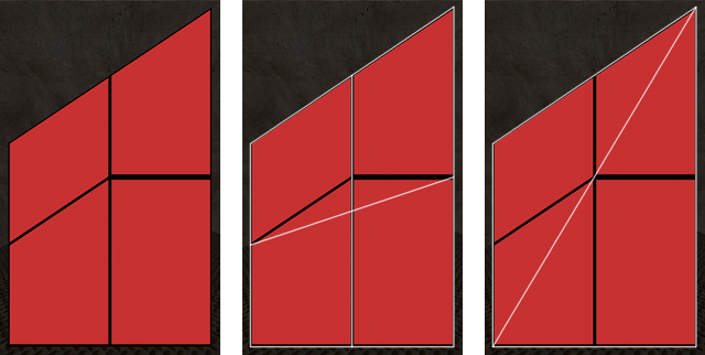
The black lines don't look like that because both GtkRadiant and Q3 will render this mesh as just two triangles, nailing down the texture coordinates at the triangle vertices and linearly interpolating between them. The rightmost image above is how GtkRadiant is triangulating the mesh. (Q3 actually chops it between the other two corners, but the result is similarly "wrong".)
That said, if you have a square or rectangular mesh with regular columns/rows this won't be an issue for most normal texturings. But if you try to do something with irregular mesh shapes or uneven control point placements you'll probably be disappointed. Especially if your mesh is a flat quadrilateral, which Q3 will always render with two triangles regardless of how many rows/columns it has.
(If I'm misunderstanding this problem, or there's a workaround, please clue me in!)
I may not have the best instruction manual here, but I'll do a run-through of the functions that the plugin provides. Unless otherwise stated, any of the functionality described below will be applied to all currently selected patch meshes once you hit "OK" or "Apply".
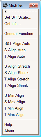
So for starters, here's what the plugin menu looks like (to the left).
The top three options open up further menus that I'll describe below. The other options are used to quickly align the S (horizontal) and/or T (vertical) axes of the texture with the edges of the mesh, using various stretch/shrink and shift operations:
"Stretch" or "Shrink" operations will stretch/shrink and shift the texture as necessary to make opposing sides of the patch mesh land on a texture boundary.
"Auto" is similar, except that it automatically chooses "Stretch" or "Shrink" depending on which one requires the least amount of change in the texture scale. "S&T Align Auto" does this for both texture axes.
"Align" operations only shift the texture without scaling it, to make one side of the patch mesh correspond to a texture boundary.
These operations do make some simplifying assumptions. They determine the necessary shift/scale factors using the current min and max S/T values on the patch mesh, and they modify the texture mapping uniformly. Probably you won't have to care about those assumptions. But if you have an unusual texturing where an edge of the mesh doesn't have a constant S/T value, then these operations are not going to "undistort" your texture mapping to snap the texture to the edge along the entire edge.
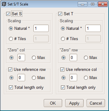
The "Set S/T Scale" dialog is what you would usually use to set up the initial texture placement on a mesh. This dialog assumes that the S coordinate of a texture will vary along a row of the mesh, and that the T coordinate will vary along a column. It has the same general kind of behavior as the texture application in Radiant's patch inspector, just with a bit more control and accuracy.
You can choose to modify the texture mapping's S coordinates, the T coordinates, or both, according to the selection of the "Set S" and "Set T" checkboxes. Leaving a checkbox unselected means that the current texture mapping along that axis will be unaffected. Selecting a checkbox means that the choices below it will be available, to determine how the texture is placed along that axis.
The options in the "Scaling" box let you choose how the texture will be sized along that axis. You can choose either a "Natural" factor or a "# Tiles". If you choose "Natural", then the factor n that you enter will set a texture mapping of 2 texture pixels per n units. (The units will be measured along the surface of the curve using adaptive ten-point Gauss-Legendre quadrature — woo!). If you choose "# Tiles", then the tiling number n that you enter will set a texture mapping that produces n texture repetitions across the mesh.
The selection in the "Zero col" or "Zero row" box chooses where the edge of the texture will be placed. You can choose to specify a particular column (for S) or row (for T), or you can select "Max" to choose the largest-numbered column or row in the mesh.
The "Use reference row" and "Use reference col" checkboxes, if selected, mean that the math that assigns texture coordinates to the mesh control points will only be performed at one row (for S) or column (for T), and then copied to the other rows or columns. This only matters if the control points have different spacing on some of the rows (or columns) than on others. As with the zero column/row selection, you can specify any row or column number as the reference, or you can choose "Max" to pick the largest-numbered row or column.
If you choose to use a reference row/column and also select the "Total length only" checkbox, then the reference is only used to determine the texture coordinates at the ends of the rows (or columns), with the spacing between control points still mattering in each row/column.
(Side note for the folks paying really close attention: if your "Scaling" behavior is set to "# Tiles", then using no reference behaves the same as using a reference with "Total length only" selected.)
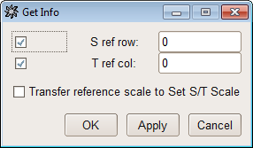
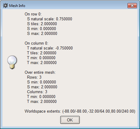
The pictures above show the "Get Info" dialog, and an example "Mesh Info" result popup that comes from using "Get Info". You will get one popup for every selected patch mesh. The "Over entire mesh" and "Worldspace extents" info will always be present; the info about a particular row and/or column will be present in the popup only if you marked that checkbox and chose a row/column number in the "Get Info" dialog.
The "Transfer reference scale" checkbox will cause the scale of the selected row and/or column to be copied into the "Natural" scale value boxes in the "Set S/T Scale" dialog. The normal use for this is to copy scaling from one patch mesh (with "Get Info") and then apply it to another (with "Set S/T Scale"). Note that if you are using the "Transfer reference scale" checkbox, you must only have one patch mesh currently selected.
This is undoubtedly the nerdiest of an already very nerdy set of tools, and I'm not sure when it would actually be useful given the limitations in Quake 3's rendering behavior described above. However it seemed a shame not to throw it in here to experiment with.
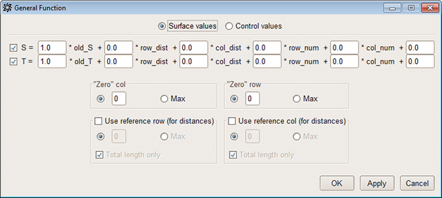
The "General Function" dialog allows you to describe each S and T value as a function of various inputs. You can choose to specify the S and T values of the control points, or you can choose to specify the values you want at the corresponding points on the surface of the curve (and let MeshTex work backwards to figure out what the control point values should be).
The "Zero col" or "Zero row" in this case marks where the row/col numbering and distance calculations begin for the purposes of those function inputs. A "reference row" or "reference col" can be used to copy the distance calculations from a given row/column to the others.
More detailed description of this particular dialog is not going to show up here any time soon; you probably won't miss out on anything by ignoring this dialog, and if you really want to use it then experimentation would be the most useful way to get a handle on it.

 ) except where indicated otherwise
 Linux Desktop Integration
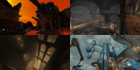 Singleplayer Starter Pack
 Steam Controller Quake
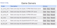 Gameserver Scripts
 quakesounds
 QL pk3 Support in 7-Zip
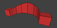 MeshTex GtkRadiant Plugin
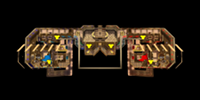 Birdseye Map Overviews
 QSmack Quake Admin